TaxiDraw Tutorial
Contents
Introduction
Installing TaxiDraw
Getting Started
Loading and Calibrating a Background Image
Starting to Edit
Tips and Tricks
The Finishing Touches - Checking Your Work
And Finally - Getting it into FlightGear
NOTE: The tutorial text has been updated to reflect the changes in TaxiDraw-0.2.x and TaxiDraw-0.3.x, but most of the screenshots were taken with version 0.1.1.
Introduction
This tutorial is aimed at newcomers to TaxiDraw. The purpose of TaxiDraw is to
add and edit taxiway and runway definitions of airports for FlightGear and
X-Plane. Both FlightGear and X-Plane share a common airport database,
maintained by Robin Peel as a
voluntary effort. This database defines the runways and taxiways as vector
data, and FlightGear and X-Plane both then either build scenery from or render
the airports in their own way. Runway data is generally available in digital
form, but taxiway data is not, and must be defined manually. Hence many
airports are defined as runways only. At the time of writing, FlightGear
scenery is built with just runways in such cases, but X-Plane adds some
heuristic taxiways in sensible locations. The author of TaxiDraw (and this
tutorial) is primarily a FlightGear user, so the tutorial will likely take a
FlightGear orientated slant.
You can of course select any airport you like to add to or edit. For this
tutorial we are going to add taxiways to an airport currently only defined by
its runways. We'll choose one in the US, due to the free
availability of suitable background images (ariel photos) for that
part of the world. Additionally, we are going to use an airport with a fairly
simple layout, in order to keep the time for the author to finish it down! The
airport I finally selected is Oxnard Airport in California, about 40 miles west
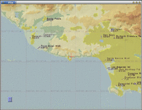
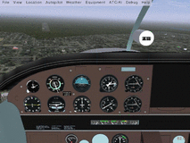
of LA. The location is shown in the Atlas screenshot below. Also shown is a
FlightGear screenshot on approach, clearly showing the lack of taxiways.
Installing TaxiDraw
Full installation instructions are on the instructions page, and not repeated here. To test that the raw data settings have been configured correctly press Ctrl-N (or File->New), and enter the ICAO code of an airport known to exist (KSFO is good). The airport layout should be brought up in TaxiDraw. Make sure that this works before proceeding.
Getting Started
Fire up TaxiDraw, and you should be presented with a blank grid. In
order to start editing the taxiways at an airport, it is first necessary to load
the runways defined for that airport from the default data file, using . This
will bring up an airport selection dialog as shown:

At the moment you need to know and enter the ICAO code of the airport you wish
to edit. Make sure you include the 'K' for US airports where needed. Hopefully
there will one day be a geographically based airport selection dialog, but for
now I can only suggest either Atlas, Google, or searching for the airport name
in runways.dat if you don't know the code.
Once the code is entered, the airport should appear. The view can be zoomed in
or out using the F4 and F5 keys, and the grid lines switched off with
Ctrl-G. The raw airport will then look much like the shot below:
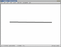
Note that by default, the runways are locked so you cannot inadvertantly change
their position or attributes. You can however view the runway properties by
right-clicking on it.
UPDATE
The latest FlightGear and X-Plane datasets now specify automatically-generated default taxiways for airports without manually entered taxiways. On loading KOXR, the layout will now look like that shown below:
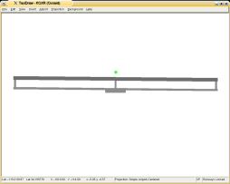
All the default taxiways currently have the same layout per runway as that shown above. Simply select them all (draw a selection box around everything) and delete before proceeding. Also note the green circular symbol - this is the location of the airport beacon. This can be moved, and the new position will be saved along with moved taxiways. Currently (v0.2) the beacon cannot be deleted using TaxiDraw.
Loading and Calibrating a
Background Image
The most convienient way to guide the layout of taxiways is to overlay the
work-in-progress over a real view of the airport. Either a plan, or an
orthorectified ariel photo is required for this. Suitable photos are available
for the entire US from terraserver-usa.com, where USGS images are hosted by
Microsoft Research, and are freely available for download and use. Thanks to
both organisations for providing this service. The most recent Linux version of
TaxiDraw can fetch and calibrate US background images in one operation
(,
then follow the instructions), but for the purpose of
the tutorial we will assume that the user has already downloaded an image, and
wishes to calibrate it manually within TaxiDraw.
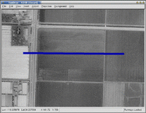
Start by loading the image using Background->Load Image. The image will initially
be displayed at it's native resolution and from the top left corner, but don't worry
about that - the scale and position will be set when we calibrate it. It will also
be hard to see the gray runway against the black-and-white image, so toggle lurid
colours with the F6 key. The screenshot below shows the image loaded and lurid-colours
enabled:
Before calibrating the image, we need to set the TaxiDraw display to use the same projection as the image. If we don't,
it will be impossible to align the image properly, since currently only position and scale is settable in the calibration process,
not alignment. TaxiDraw starts by default in a simple airport-centered projection, but 'understands' two 'proper' projections -
the Universal Transverse Mercator (UTM) projection with NAD83 datum, and the Ordnance Survery OSGB36 projection. The first is
used for most currently available USGS aerial photos of the US (beware of older photography which might use UTM but with the earlier
NAD27 datum). The OSGB36 projection is almost universally used for any UK mapping or photography. Unfortunately some available
photography is not covered by these projections - notably state-commissioned photography in the US which tends to be in the state-plane
co-ordinate system of the state concerned.
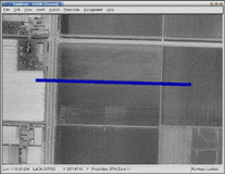
For KOXR, we will set the projection to UTM using
.
Note in the screenshot below that the X and Y values displayed in the status bar have changed, and that the
projection system used is now displayed.
The next step is to calibrate the image. To do this, you will need to know the image scale in meters per pixel. Calibration
works by first asking you the scale, and then asking you to click two matching points, the first on the FlightGear airport,
and the second on the corresponding point on the background image. The most convienient point for this is normally the corner
of one of the runways. The calibration procedure can be repeated as many times as desired until correct, indeed it is normal
to require at least two attempts since matching points can often not be seen on the first attempt since the scale is wrong.
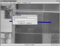
To start the calibration procedure, click on the
menu entry. A dialog will appear asking for the image scale in meters per pixel, fill it in as below. 1 m/pixel happens
to be the scale of the highest resolution USGS black and white photography available, which is what I am using for this
tutorial. Using lower resolution photography will lose some definition when zoomed in, but will zoom and pan more quickly
at high zoom levels. Note that the scale can only be set on the first calibration of an image - if you get it wrong you will
need to reload the image.
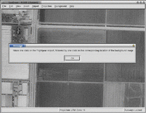
Once the scale is entered, we will be prompted by dialog to make two clicks, the first on the airport, and the second
on the corresponding background location. Note that this dialog is only displayed on the first calibration of a session,
on subsequent calibrations it is assumed that you've 'got' this, and instructions are displayed on the status bar only.
Following our two clicks we can now see the runway corner on the image (screenshot below) so we can now go ahead and
calibrate again. This time we won't have to enter the scale - it is remembered.
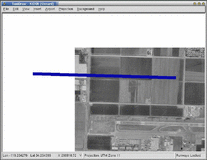
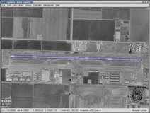
Finally, the screenshot below shows a calibration that we are happy with. Note that it often helps to use outline (non-solid)
mode to see the image runway within the FlightGear runway. The 'S' key toggles solid mode. Once you are happy with
your calibration, SAVE IT! Simply saving the work in progress to a TaxiDraw project file (*.tpj) using will save the image path, the calibration and the airport details. Reloading the project should bring one right back to the same point. It is also possible to save the calibration independently using
(), in which case the calibration is saved to a .cal file, but this is no longer required since the introduction of project files in version 0.2.
Starting to Edit
Now that our image is loaded, and the calibration set and saved, we can finally begin adding taxiways. To add our first
taxiway, either use the 'insert' menu, or just press the 'T' key. It should look like below:
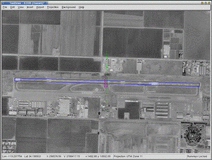
Taxiways can be dragged and rotated with the mouse or the keyboard (see Help->Keys for details). Rotation occurs when
the mouse is near to the taxiway corner, on Windows the icon will change to a cross to indicate this, but on Linux the icon
change currently doesn't work, so you'll just have to judge when its going to rotate or drag. The key command to grow or shrink
the taxiway lengthways (L/shift-L) or widthways (O/shift-O) both grow it equally both ways, so move the taxiway roughly
to the middle of where you want it...
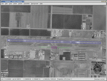
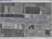
...and then grow it to the dimensions required. Final adjustment of the taxiway dimensions and heading can be set in the properties
dialog, brought up by right-clicking the selected taxiway. If you want to see the properties of an unselected runway or
taxiway, you must first select it by left-clicking, and then bring the properties up by right-clicking. The resized taxiway is shown
below:
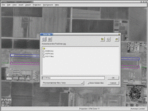
Taxiway editing can be time consuming, so SAVE YOUR WORK FREQUENTLY. Remove 'Taxiway' from the previous sentence and it applies
to a lot of computer related tasks! Save your work to a TaxiDraw project file (name defaults to airport code, in our case KOXR.tpj) using
:
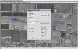
The surface type and lighting of the taxiways can also be set. By default, new
taxiways are concrete, with no lighting. Small GA airports are unlikely to have
taxiway lighting, so we will leave that as is. The choice of surface can be
tricky between asphalt and concrete. In FlightGear, asphalt surfaces are
rendered quite darkly, but in practice a lot of older asphalt surfaces appear to
be a lot lighter. Runway surface type can be looked up - Oxnard is listed as
having an asphalt runway at www.airnav.com,
but the taxiway and apron type is often more of a guess. Looking at one photo of Oxnard, it
is likely that the long taxiway and possibly all the aprons are also asphalt,
but there is a lot of contrast with the newly surfaced asphalt apron to the
right that then won't show in FlightGear. As a compromise, we'll do some of the
aprons in concrete to lighten the colour a bit. The screenshot below shows
changing the properties of the main taxiway to give it an asphalt surface:
Tips and Tricks
Sometimes you need to add a small section of apron that sticks out. Currently
there is no way to differentiate apron from taxiway, but FlightGear's scenery
building tools (called TerraGear) try to differentiate the two based on aspect
ratio and/or width. Taxiway's get a yellow line and tire marks down the middle,
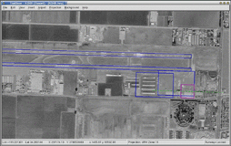
apron doesn't. Look at the screenshot below. We wanted to add a small
extension at the bottom-right of the main apron, the lower quarter of the
selected (pink) segment. Had we simply added the size needed, it would have
been interpreted by TerraGear as a taxiway, and given a centreline. By making
it a much larger square it should get interpreted as apron, and it will overlap
quite happily with the other apron. The order of overlap can be both previewed
and altered within TaxiDraw - we'll cover that later.
Zooming in and out - at high magnifications the zooming can become quite slow.
If you want to zoom in a few times then it can be speeded up by switching off
the background image (Ctrl-B), zooming and panning as required, and then
re-enabling the background image (Ctrl-B again).
Corners can be given the illusion of curvature by using two or three small
segments to 'round' the corner. Make sure the main taxiways overlap the small
segments. When working with small segments overlapped by larger ones it can be
hard to select them or to move and rotate them with the mouse. In these cases
segments can be selected by moving forwards or backwards through the segments
with the tab and backspace keys, and once selected the segment can be panned
and/or rotated with the keyboard. If the wrong taxiway is inadvertently moved,
then undo and redo (Ctrl-Z and Ctrl-Y) should work just fine.
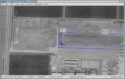

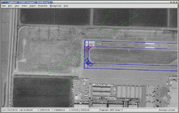
Groups of segments can be moved, or copied and pasted, together, by drawing a
bounding box with the mouse. Note that groups of segments can only be rotated
with the keypad, not the mouse. In the example shot below, the two segments
used for the lower corner have been copied to the upper corner, and then rotated
and moved into position.
The Finishing Touches - Checking Your Work
OK, now we've got an airport layout that we think is complete. There are a few
preview modes in TaxiDraw that can be used to catch errors.
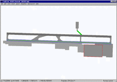
The first one is the lighting preview. We've already decided not to put taxiway
lighting in Oxnard, but I've put a deliberate mistake or two in just to show how
it looks. Lighting preview is best viewed in non-lurid colours, and the screenshot below shows
red edge lights round one section of apron, and blue edge lights and green center lights on
the main taxiway. Use the properties dialog to get rid of them.
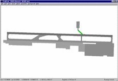
The next preview is the surface type. The shading for asphalt is darker than the shading for concrete.
(Runways are shaded darker again). Use solid shading mode to view the surface type - it can be seen in the
screenshot below which areas are asphalt and which are concrete. The green taxiway is a short section of
grass taxiway.
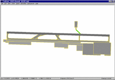
Finally, the ordering of the taxiways can be previewed to check how they will be ordered during the
FlightGear scenery generation process. To do this, toggle markings using the 'm' key. In the screenshot below,
we seem to have most of the ordering correct, but it would be nice to move the small apron to the North of the field
above the little spur taxiway leading to it. This will also serve to show the ordering tools.
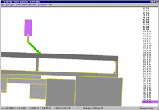
Use the 'z' key to bring up the taxiway list at the right of the screen. Note that each taxiway has two numbers associated with it.
The first number is the taxiway's position in the ordering. Number 1 will be rendered on top of number 2, and so forth. Rendering
order is maintained during save and load of the .twy file. The second number, the 'T' number, is not persistant, nor necessarily unique
to each taxiway. It exists solely to help to differentiate the taxiways as they are moved up or down in the order. The 'T' number
for a given taxiway will be persistant for the session, but they are regenerated each time the .twy file is reloaded. Note that
doing a lot of copy and pasting of taxiways will result in a lot of duplicate 'T' numbers - this is nothing to be concerned about.
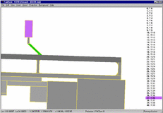
In order to manipulate the list entries, numlock must be on. The numpad 9 and 3 keys scroll the list up and down if it
doesn't fit on the screen. To select a taxiway in the list, either click on the list, or the actual airport. Numpad 8 and 2
then move that taxiway up or down the order. Remember to save the change - currently it doesn't set the outstanding-changes flag.
The screenshot below shows our layout with the apron moved up three spaces in the order. Note how it will now be rendered
above the spur taxiway.
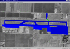
And just to show what we've done, here's a screenshot of the finished layout against the background.
And Finally - Getting it into FlightGear
OK, so now we've finished a taxiway layout. How do we make the new taxiways show up in FlightGear? Unfortunately, this
can be even more complicated than creating the layout. The easiest method is to send off the new airport layout to be included with
the master airport database. Currently the maintainer of this database is Robin Peel. Before submitting anything, please read Robin's submission guidelines here. Robin can only accept submissions in X-Plane data format - i.e. DON'T send him the TaxiDraw project file. In this case you will need to export your layout to an X-Plane format .dat file using . You will then need to wait for
updated FlightGear scenery to be made available, which will hopefully include your taxiways. The disadvantage of this approach
is that FlightGear scenery regeneration is not frequent, and it could be a while before you see your taxiways.
If you want to see your work in FlightGear immediately, it is necessary to regenerate the scenery yourself. This is done using
the TerraGear tools. There is a (currently slightly outdated) scenery building tutorial in the documentation section at
www.terragear.org, following this should get you some results. You will need to export your layout in X-Plane data format (*.dat) in order for the TerraGear airport generator to use it. Please also send your layout to Robin Peel so that it will also eventually go in the official airport database and hence the FlightGear scenery as well.
So, what does our layout look like in FlightGear? Here's another couple of screenshots, with the scenery rebuilt using the
new layout.
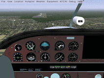
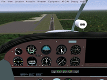
Note that the taxiways have actually been rendered by TerraGear as apron - this is because we used no lighting, and
currently TerraGear assumes that all unlit taxiway segments are apron. Hopefully one day FlightGear / TerraGear will
honor a taxiway / apron flag. Also note how well the concrete shows up against the grass background compared to the asphalt.
The obvious next step would be to add buildings and static aircraft to the airport to give a better visual reference during
approach. Blender is an open-source 3D modeller that runs on both Windows and Linux
that can create models for use in FlightGear.
FlightGear Scenery Designer is a program that can be used to place 3D objects
within the scenery.


